Time : octubre 27, 2023
Abstract: The causes of bearing current in traction motors, the damage forms, and the impact of electrical characteristics on insulated bearings were analyzed. In the application of traction motors, ceramic bearings are superior to steel bearings, as they have longer grease life and can effectively prevent electrical corrosion damage.
Keywords: ceramic bearings; Locomotive traction motor; characteristic
The traction motor is the main equipment in the transmission system of electric locomotives and electric drive internal combustion engines. The traction motor bearings are used to support radial loads caused by the mass of the rotor shaft and coupling, achieving frequent operation and stopping of cyclic operations. Due to the impact of bogie vibration during operation, the bearings must withstand a certain dynamic load. Compared with axle bearings and gear unit bearings, the calculated life of traction motor bearings is much longer. The type of bearings generally adopts cylindrical roller bearings on the gear side (transmission side), and deep groove ball bearings with support for axial movement of the rotor shaft on the reverse gear side (commutator side), which are lubricated with grease. In recent years, variable voltage and variable frequency control AC traction motors have been installed on newly manufactured electric vehicles. These AC traction motors have the characteristics of light weight, compact structure, and high-speed operation. In order to adapt to the characteristics of high-speed rotation of bearings and temperature rise of various components of traction motors, it is necessary to solve the “electrical corrosion” hazard of existing steel bearings and improve the heat resistance and durability of bearings and lubricating grease.
The basic reasons and sources for the formation of bearing current include: asymmetric magnetic flow inside the motor; Asymmetric unshielded cable setup; Quickly switch frequency converters and their common voltage. These will cause three types of currents to be generated within the bearing, namely: high-frequency shaft grounding current; High frequency circulating current and capacitive discharge current.
The main damage caused by current to bearings is “electrical corrosion”. Electrical erosion is a type of damage caused by localized melting caused by electric current passing through the very thin oil film in the rolling contact area of the bearing during rotation. The heat generated by discharge can cause local melting of the metal surface of the bearing, forming discharge marks, and the molten material particles transfer, making the local area very loose. The melted material hardens again, but is much more brittle than the original bearing material. Below the hardened material layer, there is a layer of toughened material that is softer than the surrounding material. Locomotive traction motor bearings often suffer from electrical dents, with a diameter ranging from 0 1 mm to 0 5 mm and visible to the naked eye. Electrical dents are caused by a very powerful high-voltage power supply.
The crease or washboard phenomenon (Figure 1) is formed by multiple gray lines passing through the raceway, with a shiny and blackening appearance. The formation of creases is the result of mechanical resonance caused by dynamic effects when the rolling element rolls over smaller discharge marks. Wrinkles are not the main damage caused by current passing through the bearings, but rather a minor damage to the bearings. Only after a period of time do the initial smaller discharge marks form creases. The generation of creases reduces the contact area of the rolling surface and increases the contact stress.
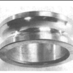
Figure 1: Folding or washing board phenomenon in the raceway
Tiny electrical dents are the most common form of current damage. Numerous small electrical dents cover the surface of the rolling element and raceway, resulting in a dull and matte appearance of the damaged surface, characterized by molten pits. The diameter of electric dents is mostly 5-8 μ m. Its true shape can only be seen through a high-power microscope (Figure 2).
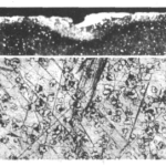
Figure 2 Cross section of small discharge marks
Current discharge can also cause changes in the structure of the lubricating grease inside the bearing, and the grease will quickly age. Local high temperatures can cause additives to react with the base oil, causing the base oil to burn or carbonize. As a result, the amount of additives used will greatly increase, and the lubricating grease will become hard and black. Rapid decay of oil is a typical fault mode caused by the passage of electric current.
At present, the solution to electrical corrosion is to set up a bypass circuit to allow current to flow to the outside of the bearing, or to insulate the surrounding area of the bearing to cut off the current. The specific methods are:
(1) Install a grounding device on the main shaft or casing of the traction motor to prevent current from passing through the inside of the bearing.
(2) Use insulated bearing racks or insulated bearings.
From the perspective of price and reliability, insulated bearings are the main method. There are roughly three types of insulated bearings used in traction motors, namely: hybrid ceramic bearings; Ceramic sprayed bearings; Resin film bearings.
In addition to the general requirements for bearings, insulated bearings for traction motors also have additional requirements for insulation performance. Mainly including:
(1) Insulation resistance stability (insulation capacity shall not significantly decrease due to changes in ambient temperature, humidity, etc.).
(2) A certain mechanical strength (there must be no fragmentation during pressing, pulling, or falling).
(3) Bearing rotation performance.
(4) The performance of alkali resistance, cleaning agents, kerosene, etc.
(5) Interchangeability with shafts, bearing boxes, etc.
When using direct current, insulated bearings act as ordinary resistors. The alumina layer is a pure insulator, therefore, an important issue is the resistance value of the alumina layer. Under the action of direct current, the breakdown voltage of the standard alumina layer is generally 1000 V, and the resistance is greater than 50 M Ω, which can effectively insulate the bearing. When using AC power, especially in the case of high-frequency current generated by gate bipolar transistor frequency converters, the insulation effect of insulated bearings must be considered. At this point, due to the rapid switching of gate bipolar transistor semiconductor devices, a high-frequency current of 5 kHz to 10 MHz is generated, which also leads to a very fast voltage increase of 5000 to 8000 V when outputted by the frequency converter/ μ s. Even up to 10 000 V/ μ S. An insulated bearing can be regarded as a capacitor, and its capacitance depends on the type of lubricant, temperature, viscosity, and thickness of the insulation film. If the voltage reaches a certain limit, the capacitor will discharge and generate high-frequency capacitive discharge current, resulting in electrical damage. Therefore, in order to prevent electrical damage to insulated bearings in high-frequency current environments, it is necessary to develop an equivalent complete set of bearing electrical circuit model diagrams, taking into account all components of the insulated bearings, calculate the resistance value of the bearing electrical system, and verify whether the system’s resistance value can meet the insulation performance requirements. Figure 3 is a schematic diagram of the equivalent electrical structure of a simulated bearing.
Accurately treating the equivalent bearing circuit as an electrical system is not a simple task. The main reasons for this are:
(1) The large number of metal elements in high-frequency electric fields have a very complex three-dimensional structure, and it is necessary to consider the possible eddy current in the structure.
(2) The contacts between the outer ring and the rolling element, as well as between the rolling element and the inner ring, generate capacitance, which varies randomly with the vibration of the bearing.
The electrical insulation layer, such as aluminum oxide (Al2O3) coating, must be designed as a parallel connection between a resistor and a capacitor. The formula for calculating the resistance value Z is
![]()
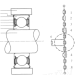
1- Bearing seat; 2- Ceramic coating; 3- Outer ring; 4- Lubricating grease; 5- Rolling element; 6- Seals or cages; 7- Inner ring; 8-axis
Figure 3 Schematic diagram of equivalent electrical structure of bearings
In the formula: R is the DC resistance of the system, Ω; C is the capacitance, F; F is the frequency, Hz.

From the above equation, it can be seen that as the current frequency increases, the term containing capacitance increases, resulting in a decrease in resistance. The insulation performance of insulated bearings decreases. To increase the resistance of the bearing, the capacitance of the coating should be as small as possible. The capacitance of an insulated bearing depends on the size of the coating surface of the bearing, the thickness of the insulation layer, and the coating material.

In the formula: A is the coating contact surface; S is the thickness of the ceramic coating; ε R is the relative dielectric constant of the insulation coating; ε 0 is the dielectric constant in vacuum.
(1) In ceramic bearings, silicon nitride ceramic rolling elements are electrical insulators. Under direct current, ceramic bearings without sealing rings or dust covers are an insulator with a resistance value of several gigabits of ohms; Under the action of high-frequency current, the ceramic rolling element of ceramic bearings acts as insulation between the inner and outer rings. Due to the very low capacitance of hybrid ceramic bearings, small raceway contact, relatively large rolling element diameter, and relatively low dielectric constant of silicon nitride materials, even in a high-frequency environment with a current frequency of 1 MHz, its resistance value is above 1 k Ω. Therefore, ceramic bearings are very effective in preventing electrical corrosion damage to bearings, especially under high-frequency current conditions.
Hybrid ceramic bearings for traction motors can cut off the current path due to the ceramic rolling element, providing insulation for the bearings and effectively preventing electrical corrosion damage; The contact between ceramics and steel will not show micro welding under poor lubrication, and will not get stuck under complete lubrication failure. The service life of hybrid ceramic bearings is 3-4 times longer than that of all steel bearings.
2023 New Week XZBRG Product Recommendation:
Cojinetes de bolas de cerámica completos construidos completamente de material cerámico. Las pistas y bolas internas/externas están hechas de nitruro de silicio (Si3N4), óxido de circonio (ZrO2) o carburo de silicio (SiC). Están disponibles como complemento completo (sin jaula) o con una jaula hecha de PEEK o PTFE. Los rodamientos totalmente cerámicos son para aplicaciones de carga media y velocidad media. No es posible lograr la redondez de los anillos interior y exterior que se encuentra con los rodamientos de acero de precisión, por lo que los rodamientos completamente cerámicos tienen clasificaciones de velocidad más bajas.
