Time : septiembre 7, 2023
Abstract : Taking the high speed ceramic bearing electric spindle used in laboratory for example, its characteristic, lubricating, the cooling system as well as electric spindle moving control are introduced. They lay a solid foundation for the application of the ceramic bearing electric spindle in the lathe.
Key words: ceramic bearing; electric spindle; characteristic; moving control
0 Introduction
The high-speed electric spindle is directly driven by an internal AC variable frequency servo motor, which can maintain good dynamic balance at high speeds The stator of the high-speed electric spindle is laminated with high-quality silicon steel sheets with high permeability, and the stator cavity is equipped with punched wire slots The function of the rotor is to convert the electromagnetic field energy of the stator into mechanical energy. It consists of three parts: the rotor core, squirrel cage, and shaft Electric spindle has the advantages of compact structure, light weight, small inertia, and good dynamic characteristics, and can improve the dynamic balance of the machine tool to avoid vibration and noise.
1 Ceramic bearing electric spindle
1.1 Characteristics of ceramic bearing electric spindle
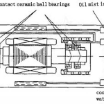
Ceramic bearing electric spindle is a high-speed electric spindle assembled with ceramic ball bearings as the spindle support. It can combine the advantages of high speed, high stiffness, high power, and long service life The structure of the ceramic bearing electric spindle system is shown in Figure 1.
Figure 1 Structure of Electric Spindle System

The laboratory electric spindle uses a hybrid ceramic ball bearing as the spindle support, which is made of silicon nitride material (Si3 N4) to make ceramic balls as rolling balls. The inner and outer rings of the bearing are still GCr15 steel rings Although the steel ball has only been transformed into a silicon nitride ball, on the other hand, the geometric dimensions of the channel have also been improved to optimize bearing performance This type of bearing not only reduces centrifugal force, but also reduces the friction between the ball and the track, resulting in lower temperature rise and better high-speed performance The most important characteristics of hybrid ceramic bearings compared to all steel bearings of the same model are as follows.
1.2 Spindle support form
The most common form of hybrid ceramic ball bearings is angular contact ball bearings, which can effectively operate at high speeds under both radial and axial loads However, axial loads can only be applied from one direction Therefore, these bearings are usually installed in pairs and preloaded to ensure the correct contact angle According to the cutting load, form, and speed, the spindle support of the laboratory electric spindle adopts the configuration shown in Figure 1 It adopts a two support structure, with the front bearing having a larger size than the rear bearing, both of which are installed in series. The front and rear supports are externally supported The use of small-sized bearings for the rear support reduces the speed factor value and has little impact on the overall rigidity of the main shaft, thus changing the working conditions and maintaining the service life of the entire shaft system The advantage is that the axial size of the spindle unit is short, the spindle stiffness is high, and the power is high, making it more suitable for large and medium-sized high-speed machine tools. Currently, most electric spindles adopt this structural form.
Grease lubrication can reduce the performance of all steel bearings, while hybrid ceramic ball bearings can safely use grease lubrication The use of a grease lubrication system eliminates the need for commonly used grease lubricated oil tanks, oil pumps, oil pipes, and transmission components, greatly simplifying the lubrication system.
Research has found that under high-speed motor operation conditions, nearly one-third of the heat generated by the motor rotor is generated, and the vast majority of the heat generated by the rotor is transmitted to the stator through the air gap between the rotor and stator. Only a small portion of the heat is directly transmitted to the main shaft and end cover, while the remaining two-thirds of the heat is generated in the motor stator.
The cooling system of high-speed electric spindle mainly relies on the circulating flow of coolant, and the flowing cold compressed air can also play a certain cooling role The laboratory adopts a circulating water internal cooling method, which is to install a sleeve with cooling liquid inside the electric spindle, which is equipped with a stator winding. The stator is cooled by continuously circulating cooling water. The cooling water is input from the water inlet on the spindle shell, and through the spiral groove on the stator cooling sleeve, it undergoes sufficient heat exchange with the motor stator. The cooling water absorbs and takes away most of the heat, and then outputs from the water outlet of the shell, Then it flows through a heat exchanger and undergoes another heat exchange with the cooling water, flowing back to the water tank, and then transported to the inlet through a water pump to achieve internal cooling of the circulating water This cooling method correspondingly increases the diameter of the shell cooling channel and the depth of the cooling chamber The temperature rise of each part of the electric spindle housing is balanced, and the heat dissipation effect is ideal.
It is quite difficult for a high-speed electric spindle to accelerate from a standstill to tens of thousands or even hundreds of thousands of revolutions per minute To ensure normal operation of the electric spindle, a certain amount of preload must be applied, which increases the resistance torque of the electric spindle. Therefore, a larger starting torque should be selected. Therefore, the starting current of the high-speed electric spindle should exceed the rated current of a regular motor by 5-7 times In this experimental electric spindle system, if a PLC is used to control the frequency converter, the electric spindle can achieve variable frequency speed regulation Integrating the linear motor (primary or secondary) with the workbench eliminates intermediate links and achieves zero feed transmission PMAC (programmable multi axis controller) controller is used to control the linear motor to achieve high-speed and precise transverse feed of the electric spindle, and PLC is used to control the servo motor to achieve longitudinal feed of the grinding wheel spindle.
In the experiment, high-speed grinding of a workpiece with a nominal diameter of 70 mm was carried out using the time base control function of PMAC, with an ellipticity of 1 mm. After processing, the ellipticity error was 0 five μ M.
When the electric spindle drives the grinding wheel to rotate at high speed, the centrifugal force generated by the imbalanced mass of the connecting rod and the grinding wheel will have a significant impact on the vibration of the electric spindle The amplitude of vibration varies greatly in various parts of the entire spindle system. Generally, the amplitude measured radially and vertically is the highest near the grinding wheel. For medium frequency electric spindles with higher rotational speeds, vibration faults often occur at the bearings. Therefore, in the experiment, we took the front bearing near the grinding wheel as the sampling point Due to the inherent characteristics of the machine tool and the fact that the vibration of the electric spindle changes with the speed of the motor, it is independent of the grinding state. At the same time, considering the feasibility of the experiment conducted in a non grinding state, we only studied the variation law of the amplitude of the acceleration vibration at the front end of the electric spindle using the INV306DF intelligent signal acquisition and processing analyzer and acceleration sensor when the grinding wheel is in the non grinding state.
According to the vibration spectrum of the front end of the electric spindle with grinding wheel extension rod and grinding wheel (omitted), it can be seen that the maximum amplitude of the grinding wheel extension rod is only 10 399 m/s 2 When the grinding wheel is used for high-speed rotation, the amplitude of vibration acceleration at the front end of the spindle does not change much, indicating that the ceramic electric spindle has good dynamic performance under high-speed operation.
More about XZBRG Silicon Nitride Ceramic Bearings:
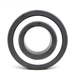
Cojinetes de bolas de cerámica completos construidos completamente de material cerámico. Las pistas y bolas internas/externas están hechas de nitruro de silicio (Si3N4), óxido de circonio (ZrO2) o carburo de silicio (SiC). Están disponibles como complemento completo (sin jaula) o con una jaula hecha de PEEK o PTFE. Los rodamientos totalmente cerámicos son para aplicaciones de carga media y velocidad media. No es posible lograr la redondez de los anillos interior y exterior que se encuentra con los rodamientos de acero de precisión, por lo que los rodamientos completamente cerámicos tienen clasificaciones de velocidad más bajas.
Silicon Nitride (Si3N4) Ceramic Bearings are lightweight, strong, and wear-resistant with excellent corrosion resistance.
