Turbocharger rolling bearing parameters and uses
1 Structure and parameters
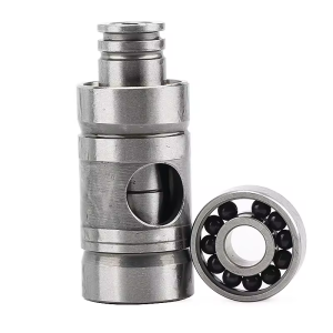
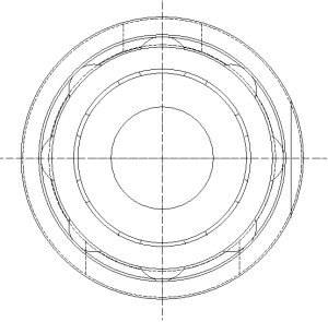
Picture 1
1.1 Contact angle
The size of the contact angle affects the orientation of the bearing to radial load and axial load. An excessively large contact angle will increase the roll-to-roll ratio, especially at high speeds, which will cause the bearing to heat up and wear severely, seriously affecting the efficiency and service life of the rolling bearing.
The rotating shaft of the automotive turbocharger reaches 140,000 to 170,000 revolutions per minute in the working state. Based on previous design experience, the contact angle of the rolling bearing of RF708 is selected as 15° (Figure 1).
1.2 Ball diameter and number of balls
When the ball diameter is constant, the more balls there are, the smaller the contact stress between the rolling element and the ferrule and the larger the roll-to-roll ratio. The ball diameter and the number of balls have a significant effect on the size of the cage beam. Excessive ball diameter and excessive number of balls will lead to a reduction in the size of the cage center diameter beam, resulting in a reduction in its strength.
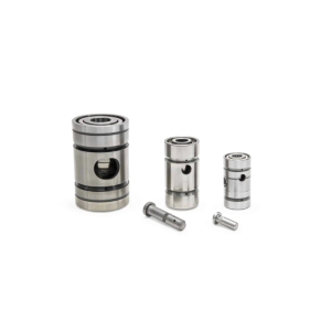
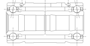
Considering the ultra-high-speed operating conditions of the RF708 bearing, especially in micro-turbojet engines, the thermal load of the bearing is the main factor affecting the bearing life, so the ball diameter is finally set to 3.969mm, and the number of balls for high-speed is 8 (Picture 2), and the number of balls for heavy load is 9.
Picture 2
1.3 Outer ring structure
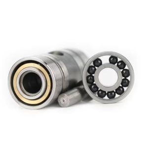
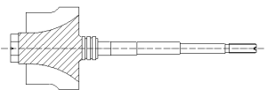
In order to facilitate installation, the outer ring adopts the form of positioning at both ends of the outer side. The two ends of the side are matched with the supercharger seat ring, and the radius of the middle part is slightly smaller than the matching part at both ends. The standard length of the outer ring is 41.65mm (Figure 1, Figure 3), and the shape is determined according to the structure of the matching turbocharger.
In view of the fact that the lubricating oil cannot enter the bearing through both ends of the bearing, oil grooves are designed on both sides of the outer ring of the bearing, and oil holes are opened radially in the grooves. The lubricating oil is sprayed to the parts that need lubrication through the oil holes. Under the condition of ensuring that the oil injection is as uniform as possible, the number of oil injection holes is set to 2.According to the outer ring structure and processing technology, the angle between the axis of the oil injection hole and the axis of the bearing is set to 74°. According to the thickness of the outer ring of the bearing, the total length of the oil injection hole is 2.2mm (Picture 1, Picture 3). The oil is treated as laminar flow when passing through the counterbore and the slender hole. When the single-side oil injection volume is 10 L/min, the aperture of the slender hole is set to 1mm.
1.4 Inner ring structure
Picture 3
In a high temperature environment, the inner ring of the bearing near the turbine end and the turbine shaft form a thermal deformation component. The inner rings of the two bearings are symmetrical in structure and have different sizes. The total length of the two inner rings is 53.73mm and 42.50mm (Picture 1, Picture 3).
The movement method after heating has a tendency to “tighten” the bearing, and the center position of the curvature of the inner raceway groove moves outward in the radial direction, so the original radial clearance is controlled within 20μm; to ensure that the axial direction coincides with the radial direction in the bearing, the rotation accuracy of the inner ring is now set to P4 level, of which the vertical accuracy of the two inner holes and the contact end surface is P2 level.
1.5 Cage
The main function of the rolling bearing cage is to isolate the rolling elements at equal intervals and improve the distribution of the bearing’s load area. When designing the cage structure, it is considered to have sufficient strength and light weight, and its structural form should be conducive to reducing friction torque and cooling, improving bearing efficiency and extending service life.
In view of the high temperature and high speed characteristics of turbocharger bearings, the ambient temperature of turbocharger bearings can reach about 300℃, so PEEK solid cages are used. While meeting the strength requirements, the thickness of the cage is as thin as possible to reduce weight and avoid crushing the oil film on the guide surface.
1.6 Guide surface
Roller body guidance can easily lead to unstable rotation of the cage at high speed, which is obviously not suitable for turbocharger bearings. Inner ring guidance and outer ring guidance each have their advantages and disadvantages.
The advantages of outer ring guidance are (the advantages and disadvantages of inner ring guidance are the opposite):
1) Lubricant can more easily enter the bearing cavity, so that the lubricant supply of the bearing is sufficient;
2) There is relative sliding between the guide surface and the outer ring, and the temperature of the outer ring is relatively low, which is beneficial to reducing the temperature of the cage:
3) The guide surface of the cage with external guidance wears more evenly, the cage is relatively larger, the strength is higher, and the vibration is smaller.
Its disadvantages are:
1) Under the action of centrifugal force and thermal expansion, the guide clearance will decrease, which is easy to increase friction and aggravate wear:
2) The size of the cage is increased, and the mass distribution radius is larger, and the moment of inertia increases.
In view of the above advantages and disadvantages, the outer ring guidance is used for high speed (Figure 2), and the inner ring guidance is used for heavy load.
Too small pocket depth and too large pocket diameter will reduce the strength of the cage. Combined with the above rules, the cage pocket diameter is taken as 1.07 times the ball diameter, the guide clearance is taken as 0.20~0.25mm, and the cage thickness is taken as 1.7mm.
1.7 Groove curvature
The contact stress on the inner raceways on both sides increases with the increase of the inner groove curvature radius. When the ball size is determined, the groove curvature radius directly determines the fit between the ball and the inner raceway. As the inner groove curvature radius increases, the fit decreases, the elliptical major axis of the elliptical contact area shortens, the contact area between the ball and the inner raceway decreases, and the contact stress increases accordingly.
In high-speed rolling bearings, the outer ring groove is also affected by the centrifugal force of the ball, and the contact surfaces are often in a boundary lubrication state. An excessively large groove curvature radius is not conducive to the formation of the lubricating oil film, resulting in an increase in friction torque and power loss. An excessively small groove curvature radius is not conducive to heat dissipation in high-speed rolling bearings.
The final optimization result is that the inner ring groove curvature radius is 2.18mm; the outer groove curvature radius is 2.10mm.
1.8 Axial clearance
The thermal deformation of the entire bearing is: the increase in the spacing between the two raceways of the outer ring of the angular contact ball bearing leads to the “tightening” of the bearing, the increase in the two raceways of the inner ring will lead to the “relaxation” of the bearing, and the expansion of the ball will cause the “tightening” of the bearing. According to the relationship between the outer ring, inner ring and ball size, the inner ring temperature is greater than the outer ring when the three are working. It can be judged that the bearing is “relaxed” under thermal stress.
According to the contact angle of the bearing, using the above thermal deformation analysis data and thermal experiments, the original axial clearance is set to 0.06~0.09mm.
1.9 Rib height
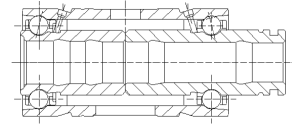
Picture 4
When the supercharger is started and shut down, the axial force borne by the double-row angular contact ball bearing is much greater than the axial force borne during stable operation; and under the starting and shutting down conditions. The axial force borne by the rotor (Figure 4) is in the opposite direction.
When the supercharger is in the starting condition, the axial force borne by the bearing increases instantly, and the axial force is directed from the compressor end to the turbine end. ; When the supercharger is shut down, the axial force borne by the bearing also increases sharply, and the axial force is directed from the turbine end to the compressor end. The axial force borne by the supercharger bearing when the supercharger is started and shut down is close to 300N, which is about 3 times that of its stable operation.
In view of the force direction of the bearing, the change of acceleration and the contact stress of the inner ring groove being particularly severe than that of the outer ring groove, the rib height of the inner ring groove is set to 1.09mm and the rib height of the outer ring groove is set to 0.68mm.
2 Application and development

Picture 5
2.1 Application of bearings
With the improvement of turbocharger efficiency and the development of matching technology, turbocharger technology has been widely used in the automotive industry. For example, after the 1.8T turbocharged engine is turbocharged for automobiles, its power will reach the level of a 2.4L ordinary engine (Picture 5).
As an environmentally friendly product with high efficiency, energy saving and high technological content, turbochargers have become the standard configuration of modern automobiles and engineering machinery because of their advantages of improving automobile engine exhaust emissions, improving the power-to-weight ratio of engines, improving engine torque characteristics, reducing fuel consumption and engine noise.
2.2 Development speed
Since 2000, the demand for superchargers in my country has increased by 30% per year. The supercharging ratio is: 100% for heavy-duty vehicles, 80% for medium-duty vehicles, 60% for light-duty vehicles, 25% for micro-vehicles, and 30% for sedans.
According to the implementation of automobile emission regulations at home and abroad, turbocharging is generally used to meet Euro I standards, turbocharging + intercooling is generally used to meet Euro II standards, and turbochargers + intercooling + high-pressure common rail + VGT are generally used to meet Euro III standards. It will promote the growth of the number of superchargers, which is manifested as follows:
First, foreign-funded enterprises that produce superchargers in domestic wholly-owned and joint ventures are increasing their production.
Second, the annual output of major national industries is roughly in the order of Honeywell, Holset, Tianyan, Fuyuan, and Kangyue.
Third, national industries are concentrated in Jiangsu, Liaoning, Shandong, Zhejiang and other places, with investments of tens of millions or even hundreds of millions of yuan.
Fourth, the mechanical processing methods of promising supercharger factories have been changed to CNC machine tools, machining centers, etc.
Fifth, the momentum of specialized production is becoming more and more obvious, which is conducive to improving product quality and market competition.
Sixth, developing independent products, improving matching technology, and paying attention to product reliability have been increasingly valued.